Abstract
The
INR Proton Linear Accelerator beam is now 10÷12 mA amplitude with pulse
duration 0.3÷200 microseconds and the repetition rate 1÷50 Hz. It
is necessary for various nuclear experiments and applications. The Beam Current
Transformers (BCT) system was modernized to provide higher sensitivity of beam
current pulse measurements. New BCT electronics was developed and installed
also. This electronics was tested in high radiation conditions of experimental
areas successfully. Besides that new wide bandwidth BCT Monitor was developed,
tested and installed for measurements both short and long beam current pulses.
The available results of beam pulse measurements are given. New BCT details are
described.
INTRODUCTION
To satisfy both fundamental and
applied research requirements it is necessary to accelerate in INR
Proton Linac 0.3¸200 ms beam pulses with rise times from 100 ns
for short pulses to 10 ms or more for long pulses. The measurements of these pulses should be realized by means of
different beam current transformers and electronics. For these aims vacuum valve
preamplifiers in accelerator tunnel were replaced by simpler and lighter integrated circuit operational preamplifiers of two types. First one
is adopted for standard BCT to measure beam pulses from 20 ms to
200 ms. Second one is adopted for Universal Beam Current Transformer (UBCT) monitor.
UBCT should measure
beam pulses in the full range of the beam parameters from 0.3 ms with time resolution better
20 ns.
BCT preamplifiers were tested for
radiation hardness at radiation conditions more hard than standard conditions
on our accelerator at INR Isotope Production Complex. Accurate non-intercepting
reliable measurement of beam charge on targets is very important for new
isotope production because target beam proton charge defines new isotope
quantity produced in target and requirements for beam time also.
BCT and UBCT construction and its electronics are described.
Results of BCT and UBCT tests on the beam are presented.
RADIATION CONDITIONS, BCT AND
UBCT PREAMPLIFIERS CIRCUIT SELECTION
Measured ratio of induced activation
levels on the surfaces of different linac parts is changed 102 times
from a few mR/hour up to Roentgen/hour. That is average proton beam current
losses at linac beam time may be as standard 1 nA/m as more
100 nA/m in some parts. For example at proton beam energy 209 MeV
γ-photons level, measured after 3 days of linac stop on linac output, was 10 mR/h and more 100 mR/h on the distance
2 m from output at the surface of beam transport line. It is supposed 209 MeV
beam halo protons are lost to the inner
metal of the vacuum chamber with 1 mrad angle of
incidence relative to chamber surface. The incidence points are distributed
uniformly over the surface of the vacuum chamber [1, 2] and all
halo protons are stopped in chamber metal. For example 250 MeV protons have
6.5 cm track length in copper before stop approximately.
If one take into account that at
energy 209 MeV one proton after stopping in copper or steel vacuum chamber
walls produces one neutron approximately, it is easy to calculate for
average 1 nA/m proton losses the neutron flux is ~105 neutrons/(cm2s)
on 1 meter distance from accelerator axis roughly. There are no any neutron
energy moderators between linac walls and preamplifiers. Then neutron flux
contains fast neutrons
in most part. Neutron distribution versus neutron energy has maximum between
0.4÷1.5 MeV with 0.7 MeV for centre energy. The distribution
grows slowly for 0.001÷0.7 MeV neutron energy from 10-2
to 2.5x10⁻² neutron/MeV/sr/proton and
falls down for 1.5÷100 MeV neutron energy range from 2x10⁻²
to 10-5 neutron/MeV/sr/proton. The
angle neutron distribution is between 0÷180 degrees. Besides
neutrons 0.002 secondary protons at 0÷180 degrees are produced by
beam proton losses. As is known [3] fast neutrons do bulk damage in silicon through the
displacement of atoms while thermal neutrons cause damage by means of nuclear
reactions. Energetic fragments and transmutations are produced in these
reactions.
Silicon transistors gain coefficient should be diminished at radiation
dose of 1014 neutron/cm2. Then it is necessary to take into account radiation hardness electronics
in these conditions. The selection of
integrated circuit preamplifiers (ICP) defines reliability of electronics mainly. For
preamplifiers test three points along linac were picked out. First one has
~10 mR/h level on vacuum chamber surface, second one~100 mR/h, third
one~300 mR/h after 3 days. Last point is at INR Isotope Production Complex
industrial premise with 160 MeV beam energy, average proton beam
100÷120 µA and high radiation and induced activation levels due to
isotope targets nearness. BCT preamplifiers were installed on 1.5 m
distance from BCT linac chamber at these 3 points in 2003 year end. UBCT
preamplifier was installed in November of 2004 year at the point with 10 mR/h
level. It was selected simple AD810N amplifiers for BCT and AD8055 amplifiers
for UBCT after some probes.
BCT AND UBCT CONSTRUCTION
As standard BCT should work with long pulses, it is no need to design wide bandwidth BCT-ICP system. The pulse duration of linac between 20µs and 200 µs demands rise times about 1 µs for BCT-preamplifier system. Small pulse damping at pulse duration is necessary to guarantee accurate measurements also. BCT turn quantity of transformer winding was decreased in 2 times for better sensitivity. Input resistance rin of BCT current-to-voltage preamplifier was decreased in 8 times, for saving constant τ = (L/rin) of current transformer (L - BCT inductance). Current-to-voltage preamplifiers on AD810N are placed in steel boxes at 1.5 m from linac. Ceramic capacitors and metal film resistors were used in preamplifiers.
BCT construction was changed for UBCT, as UBCT [4] should transform
both short (0.3 µs) and long (up to 200µs) beam current pulses. Simplified
scheme of UBCT construction is shown in Fig. 1.
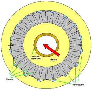
Fig. 1. Simplified
construction of UBCT.
It has 64 turns winding on
ferromagnetic high
permeability tape toroidal core. Every 4 turns are
shorted by 15 Ohm resistors. This set of resistors enables to decrease
oscillations of BCT output signal [5]. Electromotive forces and currents of all
turns are equal to each other if a beam is in a centre of a core. But there is
no equality if beam position is not centred. Beam displacement is the reason of
output signal oscillations because turn currents are not equal in this
occurrence and some waves arise in spiral line of beam transformer.
These waves interference don’t permit to see time structure of short pulses. The set of resistors should suppress this interference. Main conditions for the interference suppressing are 1) R<<Zw, where R is resistor value between turns, Zw is wave impedance of BCT spiral line without the set of resistors, 2) nR>>r, where n is quantity of R in UBCT winding, r is resistance of UBCT loading.
Reflections in cable line between UBCT and preamplifier are distortion source also. Extinguishing of these reflections waves can be done by short distance between UBCT output and ICP input or by means of suitable parallel resistor on UBCT output (a little more 75 Ohm for our cable). The rise time at input of ICP should be near 10 ns for 1 m cable.
MONITORS ELECTRONICS
The
schematic diagram of preamplifiers electronics is shown in Fig. 2 a, b.
Preamplifier of BCT is built on two AD810N transimpedance amplifier circuits.
These video amplifiers are adopted for 75 Ohm cable. There are no any
additional circuits for transmission of BCT pulses through 150 m
connecting cables in terminated loads in control room. AD810N preamplifiers for
BCT work during ~4000 hours in ≈ 35 time intervals and 4-month every year
summer vacations in test points without change of properties (preamplifiers
gains and bandwidth) within of ±1 %.
AD8055 preamplifier for UBCT works
during ~3200 hours in 10 mR/h points at the same time and beam energy.
Preamplifiers
lifetime is determined by the neutron flux
of 1014n/cm2 in 3.6x10⁷s or 10000 hour or
12.5 years for our conditions.
UBCT
electronics consists of 20 MHz preamplifier installed in the vicinity of the
UBCT and main amplifier and calibrator located outside the linac tunnel.
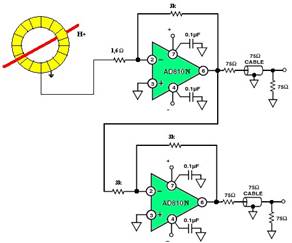
a) BCT preamplifier simplified circuit
b) UBCT preamplifier simplified circuit
Fig. 2. BCT and UBCT
preamplifiers.
The preamplifiers have one input and two symmetrical outputs for subtraction of cable interference at the input of main amplifiers. The time constant τ of flat top damping is equal to L/Rin, where L is inductance of UBCT and Rin are input resistance of the preamplifier. This time is long enough in our case to observe beam pulses up to 200 μs without distortion. The high frequency distortions are defined by time constant of wave spreading in UBCT. The waves pass through set of resistor and this process takes a few ns. Main amplifier has bandwidth 15 MHz and symmetrical input. Hence, the bandwidth of the system is defined by main amplifier. The circuits of the preamplifier and the amplifier are similar. The calibrator works out test pulses for UBCT and electronics. The level of the calibration signal on the UBCT, defined by the source of current on bipolar transistor, is equal to 20 mA and can be changed by means of regulation of emitter circuit resistor. The calibration pulses with duration 0.25μs and 200μs are used for the UBCT monitor verification.
RESULTS
Short pulses (0.3¸5 ms) are formed in the linac injection line by means of beam pulse shaping system. Amplitude of the accelerated beam pulse is equal to 10¸12 mA.
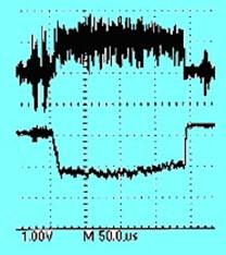
Fig. 3. Time structures of beam pulses.
The comparison between UBCT and standard BCT signals is shown in Fig. 3. It is 190 ms beam pulses from UBCT (upper pulse) and BCT respectively. Pulses were registered on 160 MeV beams.
The comparisons between BCT (lower track) and standard UBCT signals
are shown in Fig. 4 for short pulse. Some interference is seen on
Fig. 3 and 4.
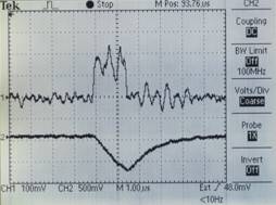
Fig. 4. Short pulse.
As easy to see standard BCT with its electronics flattens fluctuations of beam pulses. UBCT observes rise times, interference and top fluctuations in full range of the beam pulse durations from 0.3 ms to 200 ms. Additional signal integrating circuit is in main amplifier for signal flattening.
CONCLUSION
The new BCT monitors with its electronics permit to observe and measure 20÷200 µs long beam pulses without distortions of beam parameters. UBCT monitor with electronics permits to observe short and long beam pulses with high time resolution to give information about proton pulse current fluctuations and should be used for beam conditioning in case of BCT can not sure enough accuracy. The sensitivity of these devices was increased in 2 times too.
Preamplifiers can be used at INR linac radiation condition since there are no any variations of electronics parameters during long time of exploitation due to γ, neutron and proton radiation in linac.
REFERENCES
1. RADIATION DAMAGE TO THE ELEMENTS OF THE
NUCLOTRON-TYPE DIPOLE OF SIS100, E.Mustafin, G.Moritz, G.Walter, GSI, Darmstadt, Germany, L.Latycheva,
N.Sobolevskiy, INR RAS, Moscow, Russia. Proceedings of EPAC 2004,
2. N. Sobolevskiy, INR RAS, private communication.
3.
Neutron
Radiation Effects Program (NREP) at the
4.
Universal BCT Monitor for INR Proton Linac Pulse Beam. P. Reinhardt-Nikoulin,
V. Gaidash, A.Menshov, A.N.Mirzojan, A.V.Feschenko XIX
International Workshop on Charged Particle Accelerators, Ukraine, Alushta, Crimea, September 12-18, 2005.
5.
A.S.