Abstract
Residual
gas ion monitor was developed and installed on INR Proton LINAC output to
provide non-intercepting measurements of beam position, transverse section form
and beam profiles for wide energy and amplitude range. The ion transverse
section monitor details and TV image processing system are described. The
available results of beam pulse measurements are presented.
INTRODUCTION
At measurements of INR linear accelerators beam parameters
it is necessary to give particular attention to non-intercepting measurement processes,
as in most other high current accelerators (synchrotrons, cyclotrons and storage
rings) [1, 2]. That is minimization of accelerated particle beam perturbations in
processes of parameters measurements to save beam parameters and remove additional
(defined by measurement process) activation of linac transport line due to beam
scattering on beam detectors. As is well known the registration of beam
profiles by means of electrons or ions generated in interactions of accelerated
particles with residual gas molecules in accelerator vacuum chamber is just the
same non-intercepting method. It is greatly advisable to use universal beam
monitor to measure a few beam parameters, and it should be suitable for all
types of ionizing beams in wide range of beam energy and intensity also.
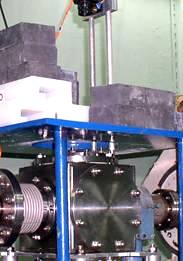
Fig.1. Output
beam line ITSM
Ion Transverse Section Monitor (ITSM) is just the device
for measurements a few transverse parameters of any ionizing beams or rays [3,
4]. Proton beam ITSMs of INR linac were destined for observation
of beams on energy 400 keV at beam transport line from injector to RFQ and 602 MeV
beam transport line on linac output (Fig.1). It gives the possibility to observe and correct next beam parameters of linac at procedures of
adjustment and exploitation:
· real form, sizes and particle distribution in transverse beam section,
· beam position and its shift from accelerator
axes.
Besides that TV registration of beam spot and computer
acquisition and processing of spot image give beam profiles. ITSM has high
sensitivity and wide dynamic range. These properties permit to measure transverse
sections of beams with intensities from a few nA/mm2 to a few
hundred mA/cm2. At present time ITSMs were
tested and used on beams of RRC “Kurchatov Institute” and INR RAS linac [5, 6]:
· proton or ion beams of 30 MeV cyclotron with average current
50 nA;
· 400 keV pulse proton current of INR linac injector with duration of
200 µs and 115 mA average pulse amplitude;
· 
pulse proton beam of linac with energy of 209 MeV and average amplitude
5 mA;
· synchrotron radiation
rays of electron storage rings with energy 450 MeV and 2,5 GeV.
ITSM can be widely used for observations, diagnosis and
corrections of beam and ray parameters both continues and pulse beams of
electrons, ions, protons, ultra-violet and gamma-rays at practically any
accelerators and sources of a radiation equipped by beam transport channels with vacuum from 10-5
to 10-8 Torr.
Double dimension distribution of accelerated beam
particles in transverse section of a beam is more informative beam
characteristic in comparison with profiles of a beam. It is not possible to reconstruct two
dimensional transverse section picture of a beam by means of two profiles from
wire scanner or multi wire grids or standard profile ionization monitors. It is need to
have special tomography software and more than 2 profiles for Radon transformation reconstruction of beam spot for these devices [7].
ITSM is simpler of traditional monitors therefore.
ITSM DESCRIPTION
ITSM consists of residual gas ion detector in vacuum
box, high voltage power supply source, TV-chamber on linac, optical cable with
interfaces for image data transmission and PC with frame grabber and software
for image processing.
The residual gas of linac beam transport line vacuum chamber
is used as ITSM detector material providing of measurement non-interception. The
device sensitivity depends on residual gas pressure and ionization losses of
accelerated particles in residual gas first of all.
The
209 MeV pulse proton beam has not fine bunched structure at 602 MeV
output of linac in our measurements.
ION DETECTOR
The method of measurements is based on preliminary
acceleration and following energy analysis of vacuum chamber residual gas ions produced by investigated particle beam. The ions
detector is equipped by extracting condenser and analysing condenser. The scheme
of multi parameter sensor, detailed distortion consideration and calculations
for beam spot registration are given in [5]. ITSM works out parameters
information in following manner: vertical extracting electric field (typically
1÷2 kV/cm) of two plane electrodes, forming plane extracting
condenser, accelerates residual gas ions in direction of lower electrode. Lower
condenser electrode has thin slit. This slit is perpendicular to beam movement
direction axes. Accelerated gas ions pass the slit and form the taped beam. The
secondary ion beam distribution along of the slit direction corresponds to
primary particle horizontal transverse distribution of investigated beam.
Energy distribution of secondary extracted ions in slit plane corresponds to
vertical particle distribution of primary beam.
The accelerated taped beam ions are analyzed on
energy by electric field of second analyzing condenser. Analyzing condenser is
turned on 45 degrees relatively to direction of accelerated particles movements.
Secondary ions move toward double micro channel plate (MCP) in analyzing
condenser. The double dimension optical image of investigated beam transverse
section is formed on phosphor screen. Phosphor screen is installed the other
side of MCP. MCP
electron charge accelerates in the space between MCP and phosphor screen and
gives light flash of screen. 45 degrees condenser provides linear relation
between image sizes and transverse sizes of investigated beam. Calculation of secondary
ion trajectory in constant electric fields of condensers shows there is no
dependence of ion coordinates on MCP input from ion charge and mass.
As easy to see spatial
resolution of ITSM is defined by slit width of extraction condenser.
ITSM SENSITIVITY AND
RESOLUTION
ITSM sensitivity at
invariable vacuum pressure depends on ionization energy losses dW/dz MeV cm2/g
of accelerated beam particles in residual gas. dW/dz
proton dependence can be calculated with Bethe-Bloch
formula for energy upper 200 MeV. For energy lower 100 MeV energy
loss can be taken from reference book [8] (blue stars on Fig. 2 a, b) or by
means of formula [9] (black line on Fig. 2a, dark blue on Fig. 2b).
-dW/dz =
(72q2*(A/W))ln(160W/(AZ)),
where q
– accelerated particle charge, W –
particle energy, A – particle mass
number, Z – atom number of gas medium
(≈7 for air). Orange and red lines are Bethe-Bloch
lines.
From energy loss comparison at
400 keV and 209 MeV follows the relation of ions numbers, produced at
these energies, is ≈ 140 (dW400 keV/dW209 MeV
≈ 140).
![]()
![]()
![]()
a)
![]()
![]()
![]()
![]()
![]()
![]()
![]()
![]()
![]()
![]()
b)
Fig. 2
The experience of ITSM application
on Kurchatov Institute cyclotron demonstrates relation of Signal to Noise more
3 is provided at average density of residual gas ions 10-16 A/mm2
or 600÷700 particle/(mm2s).
Furthermore ITSM sensitivity can be
made better by well known methods:
· Application of monochrome CCD TV camera with binning (signal adding of
matrix pixel group).
· CCD matrix cooling.
· Regulation of MCP voltage.
· Application of phosphor screen with
light radiation wave length to correspond CCD highest possible sensitivity.
· Frame background subtraction and
adding of frames.
X-ray, γ photons or neutrons are image background sources due
to hitting of MCP or CCD camera. Besides that CCD camera electronics deteriorates
by neutrons and γ radiation. For electronics saving TV camera should be
protected from these radiation sources by means of distance and hardware.
IMAGE DATA REGISTRATION,
ACQUISITION AND PROCESSING
209 MeV
proton beam transverse section images were registered by “Videoscan-285” system
[10]. It consists from CCD camera with electronic shutter, optical cable with
interfaces and the framegrabber.
Data
automatic processing is executed by special software supplied with TV-system.
The software becomes possible to vary next parameters of TV-system:
· the sensitivity of camera (binning),
· the duration of exposition time from
39 µs to 132 s,
· CCD matrix signals amplification for
brightness regulation of image.
Besides
that it is possible to start of electron shutter by external pulse. This option
solves a investigation of transverse sections and
profiles along proton current pulse at short exposition times to observe
transverse beam parameters variation.
Also
it is possible to process of images for beam profiles.
TV-camera
with monochrome CCD matrix was used for highest possible sensitivity providing.
This matrix has maximum of sensitivity at green light. Our screen phosphor
radiation has just green color.
CCD matrix
cooling becomes by Peltier TEC cell. CCD cooling decreases leakage currents of
CCD. Leakage currents deteriorate measurements especially at long time
exposition because matrix cells can be filled up of thermal electrons.
Background signals are created by these electrons.
The use of
optical cable permits long distance image signals communication (up to 15 km)
without additional signal distortions and interference. That is electromagnetic
interference can be as a rule on RF connecting cables of linac but these
interference are damped on optical connecting lines.
RESULTS OF MEASUREMENTS
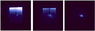
Fig. 3. Beam
conditioning process.
Working pressure is not worse 10--6 Torr in
beam transport line of INR linac commonly. It is enough for normal functioning
of the detector and MCP. On Fig. 3 209 MeV proton beam transverse section variations
are shown at process of beam transverse adjustment. This sequence of frames
permits to observe linac conditioning from big losses to small losses. There
were registered full frames at 7.7 Hz without binning. One can see black axes
are silhouetted on screen surface and thin line white 1 mm grid also.
These images were registered at 4.8÷5 mA proton pulse current,
70 µs pulse duration, 7 kV ITSM detector potential difference. The width
of extracting condenser slit is 1 mm. The least width of the tested slit
was 0.1 mm. That is spatial resolution of ITSM was ±0.5 mm. The
binning TV camera application permits increase frames frequency up to 25 Hz.
CONCLUSION
At present
time ITSM are successfully tested both high (209 MeV) and low
(400 keV) energy of INR linac proton beam.
ITSM has
high sensitivity, high signal dynamic range and lesser processing time. The
transverse section images of 209 MeV single isolated proton beam pulses
were obtained for the first time. Taking into account that the data from linac
wire scanners is received during 180 s with increasing of beam losses flow
versus 140 ms from ITSM without additional losses the advantage of ITSM
can scarcely be exaggerated at beam conditioning procedure.
It is
necessary to accentuate that registration single proton beam pulses have been
executed without binning option and adding of frames. It is mean ITSM has not
use these possibilities for sensitivity improvement. These results and
potentialities inherent in system give some hopes for the use of ITSM for
registration transverse parameters of proton beam both greater energy and
lesser intensity.
REFERENCES
1.
De Luca. IEEE Trans. Nucl. Sci., VNS-16, p.813, 1969.
2.
W.Hain et al., Proc. of EPAC-90, v.1, p.759-761,
1990.
3.
A.N.Artemiev et al., Proc. of EPAC-96, v1, p.1716-1718.
4.
V.A.Rezvov and
5.
L.I.Ioudin et al., Nucl. Instr.
and Meth.,
A405, p.265-298, 1998.
6.
S.K. Esin et al., INR RAS, RRC Kurchatov Institute,
7.
Boriskin V.N. et al., NSC KIPT, Kharkov,
Ukraine, Monitoring of the electron beam cross-section
in the air, Proceedings of RuPAC XIX, Dubna 2004, p.344-346.
8.
A.I.Pucherov et al., Tables of Mass Stopping Power and
Paths of 1÷100MeV Particles, Kiev, Naukova Dumka, v.2, p.82, 1972, (in Russian).
9.
Tsaregorodtsev M., Nucl.
El., p. 2, MEPHI,
10.
http://www.videoscan.ru/page/739