|
Brief accelerator description |
|||
|
·
High intensity linear accelerator. ·
Experimental facility. ·
Isotope production facility. ·
Conventional and auxiliary facilities. |
Outside the accelerator facility |
||
|
|
|||
|
|||
|
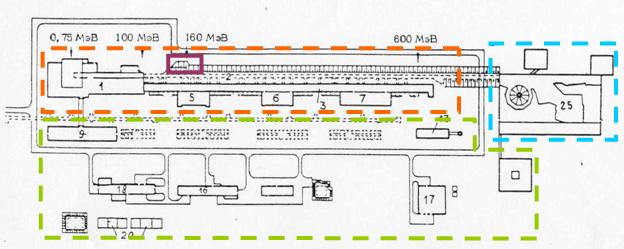
High intensity linear accelerator forms the basis of the meson
factory. The INR linac is foreseen to accelerate
protons and Н- ions up to 600 MeV
with the average current up to 500 μA. Pulse
current is 50 mA, beam pulse duration - 100 μs and beam pulse repetition rate – 100 Hz. The linac includes the injector complex, the initial part of
the accelerator (up to 100 MeV) and the high energy
part (up to 600 MeV). The intermediate energy beam
extraction is foreseen at 160 MeV. |
|||
|
|
|||
|
The injector complex
includes two injectors – protons and Н- ions, - and the
corresponding injection lines. Both
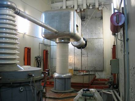
injectors use accelerating tubes and HV pulse transformers initially providing
the energy of 750 keV. The pulse current at the
exit of the injectors is tens mA, beam pulse
duration - 100 μs,
repetition rate - 50 Hz. Three 45º bending magnets enable to coincide
both beams at the third area of injection line. This area has been
reconstructed and a booster RFQ operating at 198.2 MHz has been additionally
installed to provide acceleration from 400 keV to
750 keV. Using of the booster RFQ enabled to
decrease the energy of the injectors to 400 keV
thus resulting in improvement of injector reliability for the repetition
rates up to 100 Hz as well as in increasing of the beam pulse duration up to
200 μs without pulse transformer core
saturation. |
|
||
|
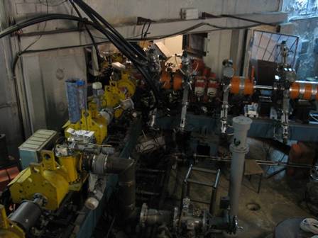
Injector complex (I,II,III- three areas of injection line; ИН+- proton source; ИН- - H- source; УТ-accelerating tube; ПМ1,ПМ2-bending magnets; Гр1,Гр2-bunchers; RFQ-booster RFQ;
Q1,Q2,Q3 –quadrupole lenses; Р1 –the first drift tube
accelerating cavity. |
|||
|
Due to economic
reasons the only proton beam was accelerated till the end of 2006. The Н- injector and the corresponding injection
line has been commissioned in December 2006 and the Н- beam has been accelerated in the initial
part of the accelerator.
|
|||
|
|
Coinciding of protons (left) and Н- ions (right) |
||
|
RFQ booster section (To the right
– entrance of the first drift tube tank) |
The beam macro pulse at the
exit of the RFQ includes about 4·104
bunches of approximately 0.8 ns duration. Six dimensional beam matching with
the downstream accelerator acceptance is provided with the four quadrupole lenses and the buncher
cavity operating at 198.2 MHz. To increase the RFQ beam capture one more buncher cavity is installed in front of the RFQ entrance.
The matched beam is injected into the initial part of the accelerator
consisting of five drift tube tanks Р1-Р5, operating at 198.2 MHz. After being
accelerated up to 100.1 MeV the beam is injected
into the high energy part of accelerator consisting of 27 disc and washer
type (DAW) accelerating cavities Р6-Р32 operating at 991 MHz. The DAW cavities are grouped in three
accelerator sections from the point of view of control and power supply, 9
cavities in each section, with the exit energies of 247.32 MeV,
423.04 MeV and 602.03 MeV.
RF power is generated by 6 triode generators and 32 klystron generators with
the output power of 3 MW and 4.7 MW correspondingly. |
||
|
For beam focusing 196 quadrupole lenses are foreseen in drift tubes of five DTL
tanks of initial part of the accelerator. High energy part utilizes 120 quadrupole doublets located between the accelerating
sections. The average pressure in the beam line is about 5·10-8 torr.
Total length of the accelerator is During the step-by-step commissioning
the beam was accelerated up to 500 MeV. At present
the energy is limited by the amount of klystrons available and capabilities
of their production in industry. The rest of the cavities up to final energy
have been conditioned with a movable klystron. |
|||
|
|
|
||
|
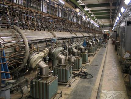
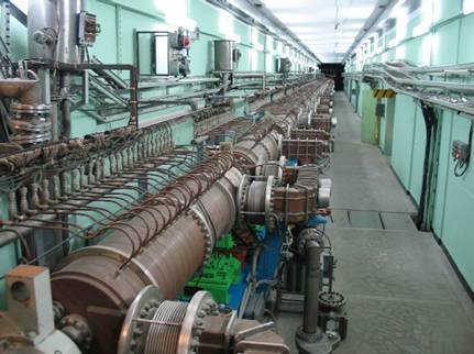
Initial part of accelerator |
High energy part of accelerator |
||
|
The main criterion of proper accelerator tuning is minimum beam loss.
Usually the value of beam loss must not exceed few tenth of per cent in the main
part of the accelerator. The system to observe and monitor beam loss provides
a possibility to decrease the loss to about 0.1 % thus enabling operation of
the accelerator with beam intensities up to 120 μA. The
pulse intensity is about 20 mA.
A variety of beam tuning
techniques has been developed and implemented: acceptance scan, delta-T
procedure, beam correction and matching procedure etc. The method of fine
energy adjustment with accurate time of flight measurements, about ±0.2%, has
also been developed and implemented. A detector for longitudinal beam profile
measurement has been developed. This detector has been also developed for
several accelerator laboratories in To provide time of flight neutron measurement as
well as the measurement in a spectrometer on slowing-down in lead generation
of beam short pulses is provided using a traveling wave beam deflector
installed in injection line. One or two pulses with adjustable duration
within the range from 0.3 μs to 50 μs and adjustable delay can be provided. The beam line to extract the beam to the isotope
production facility at 160 MeV has been designed
and built. The beam is deflected by two dipole magnets and approximately |
|||
|
|
|
|
|
|
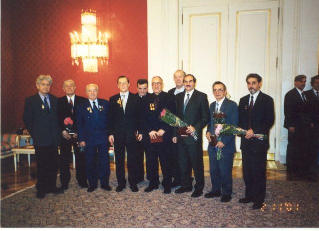
Group of laureates in the White
House of Russian Government after receiving the prize of Russian Government
in science and technology (From left to right: A.P.Fedotov, E.D. Lebedev, S.K.Esin, V.A.Matveev, B.I.Bondarev, A.N.Tavhelidze, N.I.Uksusov, L.V.Kravchuk, O.D.Pronin,
V.L.Serov) |
|||
 Proton
injector
Proton
injector