Operation and Research Activities
at the INR Accelerator Complex
|
||||||||||||||||||||||||||||||||||||||||||||||||||||||||||||||||||||||||||||||||||||
|
L.V.Kravchuk, Institute for Nuclear Research of RAS, 60-th October anniversary pr. 7a, |
||||||||||||||||||||||||||||||||||||||||||||||||||||||||||||||||||||||||||||||||||||
|
Abstract The
INR Accelerator Complex based on the high-intensity proton linear accelerator
is under operation. Status of the Linac and main
user facilities is given in the paper. Participation of the INR accelerator
team in some international collaborations for particle accelerator research,
development and construction is briefly described. |
||||||||||||||||||||||||||||||||||||||||||||||||||||||||||||||||||||||||||||||||||||
Introduction
The INR Accelerator Complex including a
high-intensity proton Linac, Neutron research
complex, Isotope production facility and Beam therapy complex is located in
science city Troitsk In
recent time just two high-intensity high-power proton/H-minus linacs were under operation: LANSCE (former LAMPF) at
LANL, |
||||||||||||||||||||||||||||||||||||||||||||||||||||||||||||||||||||||||||||||||||||
|
||||||||||||||||||||||||||||||||||||||||||||||||||||||||||||||||||||||||||||||||||||
|
First superconducting proton linac in
the world 1.3 GeV 1.4 MW SNS Linac
at ORNL, USA is now more powerful proton linac in
the world (about 500 kW at the moment).
Construction was complete in 2006 and now the machine is in
commissioning stage to reach the design parameters as well as first
experiments at the instruments around the target are in progress. This
facility is dedicated for nanomaterials research by
neutron scattering methods.
J-PARC (JAERI/KEK, So use of the INR proton Linac in a multi-purposes complex is absolutely actual
now. |
||||||||||||||||||||||||||||||||||||||||||||||||||||||||||||||||||||||||||||||||||||
|
|
||||||||||||||||||||||||||||||||||||||||||||||||||||||||||||||||||||||||||||||||||||
Operation of the INR
proton Linac
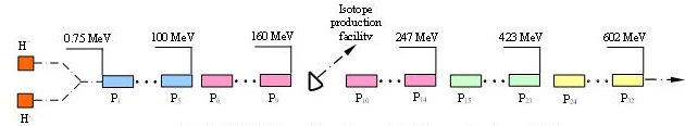
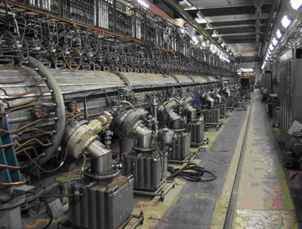
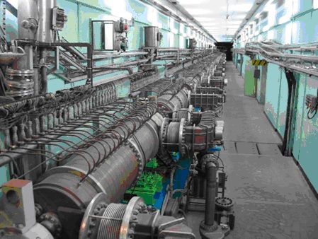
The INR proton Linac (Fig.1,2,3) consists of proton and H-minus injectors, low energy beam transport lines, 750 keV booster RFQ, 100 MeV drift tube linac DTL and 600 MeV coupled cavity linac CCL (Disk and Washer accelerating structure). There are six 198.2 MHz DTL RF stations and 31 991 MHz CCL RF stations including one reserve station per each from five Linac sectors. The detail description of the INR proton Linac is given in /1,2/. Designed, achieved and operational Linac parameters are summarized in Table 2. The Linac started
its regular operation 1993 and provided till now 79 beam runs with about
2000-2400 hours per year. It’s very important that reliability of operation
is rather good now by means of many technical and organizational improvements
– about 80-90% (percentage of a beam on user’s target from a full beam run
time). Main criteria for the Linac tuning before
start of high-intensity operation mode
(more 100 µA average current) is that the beam losses should be not more than
0.1%. Tuning procedure normally take 3-4 shifts and includes phase scan for
the DTL part and ∆t-procedure for the CCL one. |
||||||||||||||||||||||||||||||||||||||||||||||||||||||||||||||||||||||||||||||||||||
|
||||||||||||||||||||||||||||||||||||||||||||||||||||||||||||||||||||||||||||||||||||
|
|
||||||||||||||||||||||||||||||||||||||||||||||||||||||||||||||||||||||||||||||||||||
|
The features of accelerator operations
for main Linac
users are as follows: ∙
Isotope production – high intensity mode, average current from 70 to 120 µA.
Main problems are beam loss and operation reliability. ∙
Neutron complex – short beam pulse 0.3 - 60µs, high intensity. Problems to be
solved are beam diagnostics, phase stabilization in phase reference lines,
accelerating fields stabilization, transient processes. ∙
Proton therapy – small pulse and average current about 1 µA require a special
beam diagnostics and additional phase reference lines stabilization system. |
||||||||||||||||||||||||||||||||||||||||||||||||||||||||||||||||||||||||||||||||||||
|
The tasks and problems to be solved for a
further Linac operation take place because of the
machine age as well as common situation in industry. First of all a number of
klystrons on hand now limiting proton energy by 209 MeV
instead of designed 600 MeV. Many efforts have to
be done to restore the klystron production in industry or to have an
appropriate funding to design and produce it at some firm abroad (we have
offers from Toshiba and Thales). Stopping of some
RF and modulator tubes production require replacement them by available ones
with corresponding modernization of rf stations
(for instance tube GI-54A will be replaced by GI-71A, GI- 51A
by GI-57A). Some drift tubes of the DTL part should be repaired or replaced
by new ones and it’s in progress now. |
||||||||||||||||||||||||||||||||||||||||||||||||||||||||||||||||||||||||||||||||||||
|
|
||||||||||||||||||||||||||||||||||||||||||||||||||||||||||||||||||||||||||||||||||||
|
The nearest tasks we are planning for
the Linac are as follows: -
completion of H-minus injector and low energy beam transport line; -
bringing a process of two beam operation (protons and H-minus
simultaneously) to routine operation; -
modernization of 160 MeV intermediate
extraction region, installation of new kiker-magnet,
providing of flexible beams distribution between experimental and isotope
production facilities; -
modernization of the DTL RF System; -
doubling of the repetition rate to 100 Hz; -
increase of proton energy as more klystrons become available. At the same time upgrade possibilities
for the INR proton Linac have to be considering
towards a modern spallation netron
source with power about 1 MW or more. It could be replacement of a few CCL
modules by superconducting cavities in the accelerator tunnel to increase
energy to about 1 GeV
/3/ or increase a beam pulse length to 1 ms or something else in dependence
from a possible budget and time scale. |
||||||||||||||||||||||||||||||||||||||||||||||||||||||||||||||||||||||||||||||||||||
Experimental Area
and the Linac Applications
Experimental Area at the exit of
the proton Linac consists of Neutron complex and
Beam therapy irradiation facility. Systems of beam formation and
transportation to targets of the experimental facilities at the moment are under modernization,
including beam diagnostics and control systems. Neutron research complex includes three
main facilities: Spallation neutron source IN-06 with
a number of multipurpose instruments, Spectrometer on neutrons slowing down
in lead LNS-100 (100 tons of pure lead) and Time of flight TOF spectrometer
RADEX. The facilities design, experimental possibilities and first results
are described in detail in /4/. Purpose of the Beam therapy complex is
oncology tumors treatment by proton beam and/or by γ irradiation. Proton beam with energy from 70 to 250 MeV in dependence from a tumor
depth is transporting to the irradiation chamber, γ irradiation is providing
by 6 MeV electron linac
SL-75-5 /5/. Low intensity of the proton beam require a special diagnostics
and control system. In nearest future there is a plan to use H-minus beam
from the INR Linac to provide a parallel work with
Neutron complex / Isotope production facility. Construction of the first turn
of the Beam therapy facility is complete in 2007 and accepted by the State
Commission. Commissioning as well as a lot of formalities to start a regular
treatment process for patients are in progress now.
The proton Linac has an interruption in the
regular accelerating structure at 160 MeV where a
beam is turning by two bending magnets to the Isotope production facility IPF
/6/. Special beam position and shape as well as a control system for precise
tuning of the beam on the target have been developed and implemented. IPF is
operating mostly for production of Sr-82 for positron-emission tomography.
Many other isotopes for medicine and industry such as Pd-103, Ge-68, Se-72,
Cu-67, Sn-117m, Ac-225 etc could be produced at the IPF in commercial scale. |
||||||||||||||||||||||||||||||||||||||||||||||||||||||||||||||||||||||||||||||||||||
INR particle
accelerators research activity for international collaborations
INR accelerator team is widely
participating for a long time in many collaborations for the particle
accelerators development at many Laboratories abroad. For the LHC which is under commissioning at
CERN now INR successfully complete three addendums to the Since 2002 INR participates at the SNS ( Collaboration with DESY, Optimization of the Annular Coupled
Structure for J-PARC Linac (KEK/JAERI, More recent activity is INR participation
in X-ray Free Electron Laser XFEL International collaboration. INR suppose to
be responsible for design and construction of Transverse Deflecting Structure
TDS for three special diagnostics sections of the XFEL to measure
longitudinal beam profile, the slice energy spread and the slice emittance.
The list of other INR collaborations for particle accelerators
research and development is rather large (LANL, TRIUMF, ANL, FNAL, etc) and
can’t be described in detail in this paper due to a limited volume. |
||||||||||||||||||||||||||||||||||||||||||||||||||||||||||||||||||||||||||||||||||||
Conclusion
The INR proton Linac
is under operation with about 2000 hours per year. Proton energy at the
moment is 209 MeV limited by a number of klystrons
on hand, average current is till 150 µA. The main Linac
users are Neutron research complex, Isotope production facility and Beam
therapy complex.
INR is actively participating in many international particle
accelerators collaborations for R&D, construction and commissioning. |
||||||||||||||||||||||||||||||||||||||||||||||||||||||||||||||||||||||||||||||||||||
Acknowledgments
This work represents collaborative efforts of the INR Accelerator Complex and Experimental Area Divisions, other divisions, groups and people. Author thanks to all of them. A partial list of people with a personal gratitude is mentioned here: V.Matveev, A.Feschenko, V.Serov, V.Paramonov, M.Grachev, B.Zhuikov, E.Koptelov, S.Akulinichev and others. |
||||||||||||||||||||||||||||||||||||||||||||||||||||||||||||||||||||||||||||||||||||
References
[1] L.V.Kravchuk. INR proton Linac
operation and applications. Nucl. Instr. and Meth. A 562 (2006), 932-934. [2] L.V.Kravchuk.
Operation of and prospects for MMF accelerator complex. Radiation Physics and Chemistry 75 (2006), 920-922. [3] L.V.Kravchuk, P.N.Ostroumov.Upgrade Possibility of INR Proton Linac for production 3 MW beam. Particle Accel.
Conf. PAC 1999, [4] E.A.Koptelov, L.V.Kravchuk. A Neutron Complex of INR RAS – A Facility
Status Report. ICANS-XYIII, April 2007, [5] S.V.Akulinichev,
L.V.Kravchuk, V.A.Matveev.
Radiological Centre based on INR proton Linac. XIX
RUPAC, October 2004, [6] B.L.Zhuikov et al. Target irradiation facility and targetry development at 160 MeV
proton beam of [7] A.V.Feschenko
et al. Longitudinal beam parameters study in the SNS Linac.
Particle Accel. Conf. PAC 2007, [8] L.V.Kravchuk, V.V.Paramonov, V.A.Puntus. The
Cold Model of the CDS structure. XIX LINAC Conf., 1998, [9] V.V.Paramonov
et al. The PITZ booster cavity – a prototype for the ILC Positron injector Cavities. Particle Accel.
Conf. PAC 2005, [10] V.V.
Paramonov. The Coupled Cell Structures Parameters
for the Large Bore Hole Diameter. KEK report 2002-5, KEK, |
||||||||||||||||||||||||||||||||||||||||||||||||||||||||||||||||||||||||||||||||||||